
SOLVED PRACTICE LIBRARY · PRINT-FRIENDLY ANSWER KEY
Network Theory Set 01 — solutions and answer key.
All 17 original educational explanations and redrawn figures, presented as a companion to the timed online test.
Editor’s note: These are independent AI-assisted educational solutions adapted from the uploaded question collection and should be reviewed by an Electrical Engineering educator before final publication. They are not official GATE answer keys.
QUESTION 01 · 2018
AC power transfer
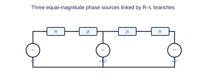
- The source phase angles are 0°, +10°, and +5° respectively.
- For an interconnection dominated by inductive reactance, real power flows predominantly from a bus with a larger voltage angle to one with a smaller angle.
- Source 2 leads both source 1 and source 3, so it delivers real power to both. Sources 1 and 3 absorb power (negative source output).
- Thus P₁ < 0, P₂ > 0, P₃ < 0. Resistive losses are small but do not reverse these signs.
Exam insight: For lossless equal-voltage inductive links, Pᵢⱼ ≈ (V²/X) sin(δᵢ − δⱼ); inspect the phase angles before solving the full circuit.
QUESTION 02 · 2009
Wheatstone bridge
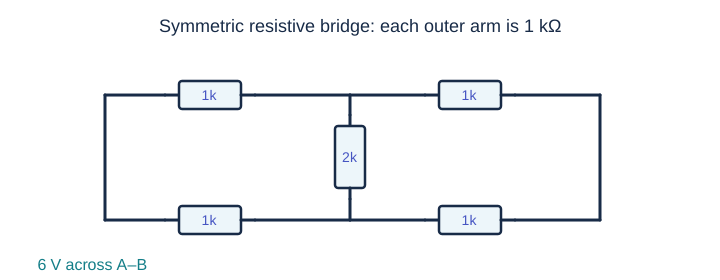
- The upper and lower A–B branches each contain identical series resistors of 1 kΩ + 1 kΩ.
- The midpoint voltage in both branches is exactly half the supply, so V_C = V_D = 3 V (relative to the low-potential rail).
- The bridge resistor sees zero potential difference: I_{CD} = (V_C − V_D)/(2 kΩ) = 0.
Exam insight: A bridge is balanced when R₁/R₂ = R₃/R₄. The bridge-arm resistance then does not affect the midpoint balance.
QUESTION 03 · 2021
Dependent-source Thevenin
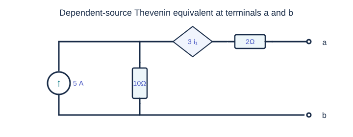
- With a–b open, no current flows through the 2 Ω resistor. The 5 A source therefore drives i₁ = 5 A through 10 Ω.
- The main node is V = 10×5 = 50 V. The dependent source adds 3i₁ = 15 V, giving V_th = 65 V.
- To calculate R_th, open the independent current source and apply a 1 A test current entering terminal a. Then i₁ = 1 A, the 10 Ω drop is 10 V, the controlled-source rise is 3 V, and the 2 Ω drop is 2 V.
- The test voltage is V_test = 10 + 3 + 2 = 15 V, hence R_th = 15 Ω.
Exam insight: Keep dependent sources active when finding Thevenin resistance. Use a test current or test voltage.
QUESTION 04 · 2010
Capacitor switching
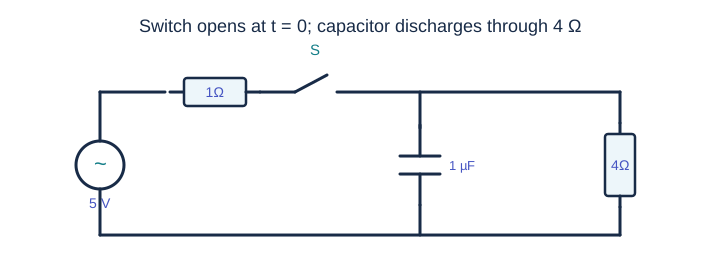
- Before switching, the capacitor is an open circuit at DC steady state. The 1 Ω and 4 Ω resistors form a voltage divider.
- The capacitor voltage is V_C(0⁻)=5×4/(1+4)=4 V.
- Capacitor voltage is continuous: V_C(0⁺)=4 V. When the switch opens, the capacitor discharges through only the 4 Ω resistor.
- The initial discharge-current magnitude is |i_C(0⁺)|=4/4=1 A.
Exam insight: For switching circuits, first obtain the pre-switch steady state, then apply capacitor-voltage continuity.
QUESTION 05 · 2022
Balanced three-phase loads
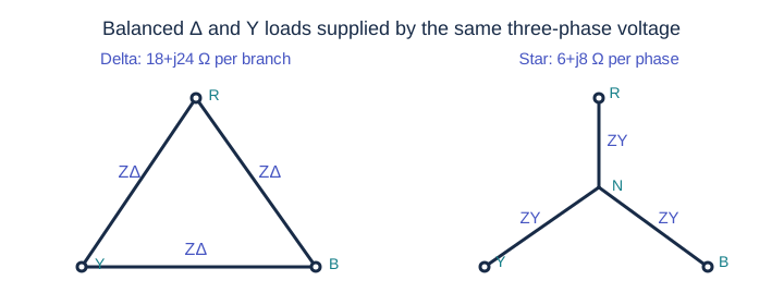
- Convert the delta load to its equivalent balanced star: ZΔ,Y = ZΔ/3 = (18+j24)/3 = 6+j8 Ω.
- This equivalent load is in parallel with the existing star phase impedance 6+j8 Ω. Consequently Z_phase = (6+j8)/2 = 3+j4 Ω, whose magnitude is 5 Ω.
- The phase (line-to-neutral) RMS voltage is V_phase=(100√3)/√3=100 V.
- Hence the star-equivalent line current is I_L=100/5=20 A.
Exam insight: For balanced three-phase circuits, convert Δ to Y first to simplify per-phase analysis.
QUESTION 06 · 2014
Positive-sequence phasors
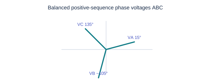
- With positive ABC sequence, V_BN=10∠(15°−120°)=10∠−105° V.
- For a positive-sequence system, the line-to-line phasor V_BC leads the phase phasor V_BN by 30° and has √3 times its magnitude.
- Thus V_BC=10√3∠(−105°+30°)=10√3∠−75° V.
Exam insight: In positive sequence, V_AB=√3 V_AN∠30°, V_BC=√3 V_BN∠30°, and so on.
QUESTION 07 · 2013
Complex power signs
- The given current direction is from the load to the source. Under passive sign convention, the current entering the load is I_L = −10∠−150° = 10∠30° A.
- The load’s complex power is S=V I_L* =100∠60° ×10∠−30°=1000∠30° VA.
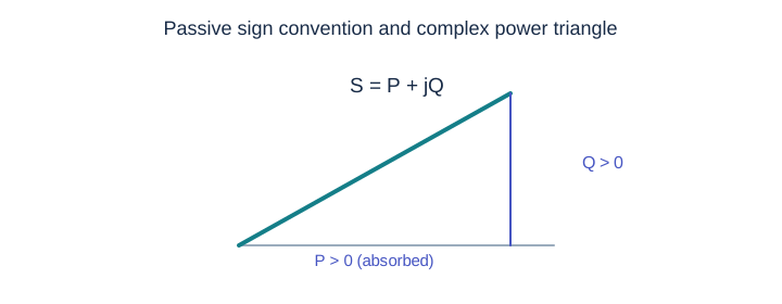
- Therefore P=1000 cos30°≈866 W>0 and Q=1000 sin30°=500 var>0. Both are absorbed.
Exam insight: If a measured current arrow points out of the load, reverse its direction before computing absorbed complex power.
QUESTION 08 · 2025
Ideal network elements
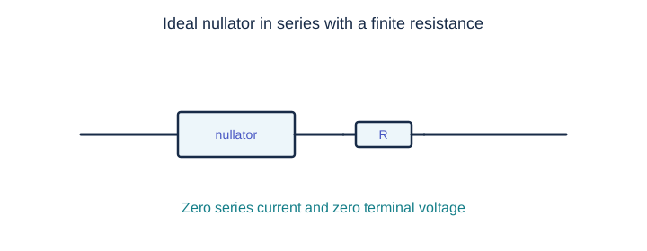
- Series elements carry the same current. The nullator requires i=0, so the resistor also carries zero current and has v_R=iR=0.
- The nullator itself has v_N=0. Thus the series pair has v_terminal=v_N+v_R=0 and i_terminal=0.
- Both nullator constraints remain, so the equivalent is a nullator rather than a generic open or short.
Exam insight: A nullator requires both v=0 and i=0. An ordinary short fixes only v=0; an ordinary open fixes only i=0.
QUESTION 09 · 2026
First-order RC step response
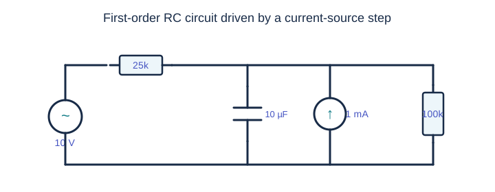
- Before t=0, the 1 mA source is off and the capacitor is open at steady state. Voltage division gives v_C(0⁻)=10×100/(25+100)=8 V.
- After the source turns on, the DC node satisfies (v−10)/25k + v/100k = 1 mA; solving gives v_C(∞)=28 V.
- With ideal voltage and current sources deactivated for resistance, R_th=25k∥100k=20 kΩ. Therefore τ=R_th C=20k×10µ=0.20 s.
- Use v_C(t)=28+(8−28)e^(−t/0.2). At 0.5 s this is 28−20e^(−2.5)=26.36 V.
Exam insight: Check both endpoint values (at 0⁺ and ∞) before evaluating the exponential.
QUESTION 10 · 2015
Two-port Norton equivalent
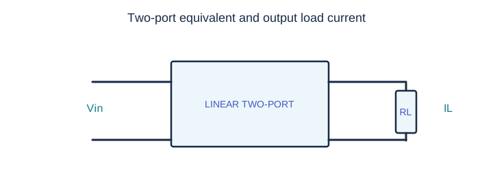
- For the same linear two-port, short-circuit current scales with input voltage: I_N(5 V)=4×5/10=2 A.
- Let the Norton output resistance be R. With a 1 Ω load, current division gives 1.25=2×R/(R+1), so R=5/3 Ω.
- For a 3 V input, the Norton current is I_N(3 V)=4×3/10=1.2 A.
- With the 2 Ω load, I_L=1.2×(5/3)/(5/3+2)=6/11≈0.5455 A.
Exam insight: Norton equivalent makes short-circuit-current measurements especially convenient.
QUESTION 11 · 2016
RC discharge and charge
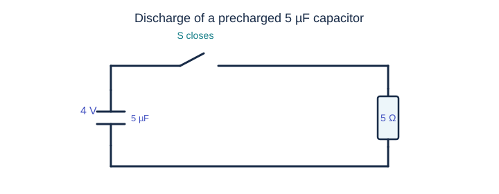
- The RC time constant is τ=RC=5×5 µs=25 µs.
- The initial capacitor charge is q(0)=CV=5 µF×4 V=20 µC.
- During discharge, q(t)=20e^(−t/25µs) µC.
- The charge lost is q(25µs)−q(100µs)=20(e^(−1)−e^(−4))≈6.9913 µC.
Exam insight: Charge lost is the difference between charge at the two specified instants—not the initial charge minus the final charge.
QUESTION 12 · 2020
RC zero-crossing
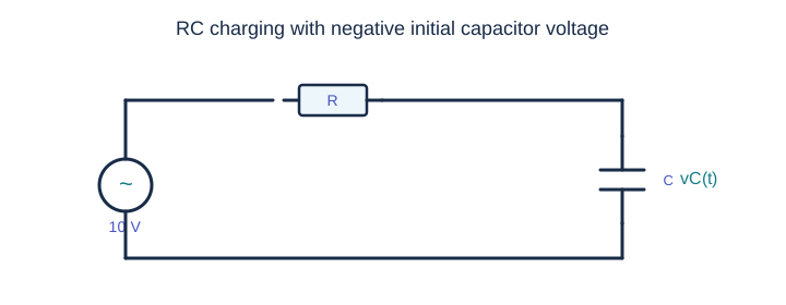
- For a first-order charging circuit, v_C(t)=10+(V₀−10)e^(−t/τ).
- At a zero crossing t=aτ, setting v_C=0 gives V₀=10(1−e^a).
- Originally V₀=10(1−e^0.4)=−4.91825 V. To cross at 0.2τ, the new initial voltage must be V₀′=10(1−e^0.2)=−2.21403 V.
- The requested absolute percentage change relative to the original initial voltage is 100×|V₀′−V₀|/|V₀|≈54.98%.
Exam insight: Both initial voltages are negative. Take the absolute change and divide by the magnitude of the original initial voltage.
QUESTION 13 · 2007
Inductor current continuity
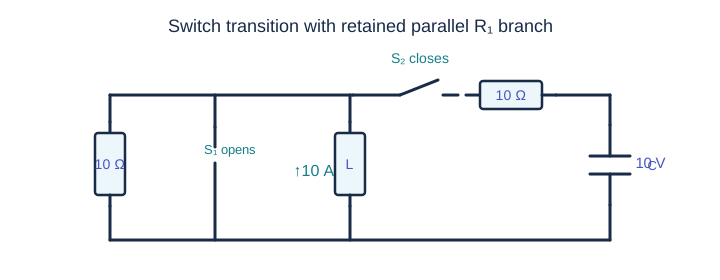
- The inductor current cannot jump. It remains 10 A upward at t=0⁺. The capacitor voltage also cannot jump and remains 10 V.
- S₁ is open, but the parallel 10 Ω resistor R₁ remains connected. The inductor injects 10 A into two paths: R₁ and the R₂–C branch.
- The shunt switch has opened, so the two 10 Ω resistive paths must both appear in KCL at the inductor top node.
- KCL gives V_L/10+(V_L−10)/10=10, yielding V_L=55 V and i_C=(55−10)/10=4.5 A.
Exam insight: Always freeze inductor current and capacitor voltage at switching. Retain both 10 Ω branches when setting up post-switch KCL; S₁ is a shunt switch, not a switch in series with R₁.
QUESTION 14 · 2017
Maximum average power transfer
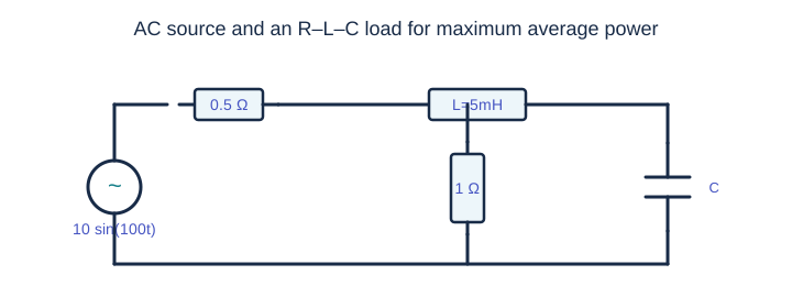
- The angular frequency is ω=100 rad/s, so X_L=ωL=100×0.005=0.5 Ω.
- Let x=ωCR with R=1 Ω. The parallel impedance is Z_(R∥C)=1/(1+jx)=(1−jx)/(1+x²) Ω.
- To match the real source resistance R_s=0.5 Ω and cancel its zero reactance, require Re(Z_load)=0.5 and Im(Z_load)=0. This gives 1/(1+x²)=0.5 ⇒ x=1.
- Thus C=x/(ωR)=1/(100×1)=0.01 F = 10 mF. At x=1, the parallel branch has reactance −0.5 Ω, canceling the series inductor.
Exam insight: For maximum AC power transfer, match the load impedance to the complex conjugate of the source impedance.
QUESTION 15 · 2011
Dielectric loss and tan δ
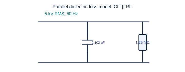
- In the parallel model, resistive real-power dissipation is P=V_rms²/R_p=(5000²)/(1.25×10⁶)=20 W.
- The dielectric loss tangent is the ratio of resistive conductance to capacitive susceptance: tan δ=G/B_C=(1/R_p)/(ωC_p)=1/(2π f R_p C_p).
- Substituting values gives tan δ≈1/(2π×50×1.25×10⁶×0.102×10⁻⁶)≈0.02497≈0.025.
Exam insight: Use RMS voltage in the resistor power formula. Loss tangent is dimensionless.
QUESTION 16 · 2012
Two-port data interpretation
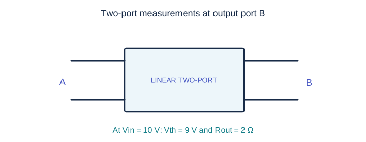
- For 10 V input, represent the output by V_th in series with R_th. Measurements give V_th/(R_th+1)=3 and V_th/(R_th+2.5)=2.
- Solving 3(R_th+1)=2(R_th+2.5) gives R_th=2 Ω and V_th(10 V)=9 V.
- With input 6 V and load 1 Ω, the implied output open-circuit voltage is V_th(6 V)=(7/3)(2+1)=7 V.
- Using the affine relationship through these measurements, V_th(V_A)=0.5V_A+4. Therefore V_th(8 V)=0.5×8+4=8 V.
Exam insight: Accuracy note: the given 6 V measurement is inconsistent with a homogeneous, source-free linear two-port (which would scale output by 6/10). The specified measurements imply an internally biased/affine response. This solution follows the measured data and the intended source answer; students should be told about the assumption.
QUESTION 17 · 2012
Two-port output loading
- From the two measurements at 10 V input, the output Thevenin voltage is V_th=9 V and output Thevenin resistance is R_th=2 Ω.
- The new load is R_L=7 Ω. Therefore I_L=V_th/(R_th+R_L)=9/(2+7)=1 A.
Exam insight: Once a Thevenin equivalent has been determined for a fixed input, changing the load requires only a series-current calculation.