Independent educational sample. Questions are paraphrased from the uploaded practice compilation (source years are shown). The solutions are AI-assisted, independently reasoned drafts and should receive educator review before wider publication. This is not an official GATE answer key. Negative marking is applied only to MCQs.
READY WHEN YOU ARE
Network Theory · Set 01
Work through the questions at your own pace, or finish within the suggested 50 minutes. Your responses are saved on this device. Solutions unlock after you submit.
✓ MCQs and numerical answers✓ Redrawn circuit diagrams✓ Auto-graded sample answer key✓ Detailed reasoning and exam tips
No sign-in required.
YOUR ATTEMPT
0 of 17 answered
50:00
QUESTION 01 OF 17
AC power transfer
1 markMCQ
Source reference: GATE EE 2018 · EE Q8 · reworded for independent practice
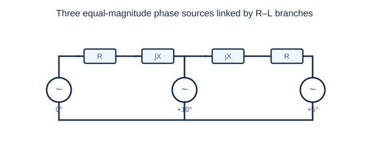
Three equal-amplitude AC voltage sources are interconnected through two identical series R–L branches, as shown. Their instantaneous voltages are v₁(t) = 100 cos(ωt), v₂(t) = 100 cos(ωt + π/18), and v₃(t) = 100 cos(ωt + π/36). The system is at steady state and R ≪ ωL. Taking P₁, P₂, P₃ positive when the respective source delivers average power, identify the correct sign pattern.
Clean schematic redrawn for this practice question (not an official exam graphic).
YOUR RESPONSE
Detailed solution and exam tip
Answer: C
The source phase angles are 0°, +10°, and +5° respectively.
For an interconnection dominated by inductive reactance, real power flows predominantly from a bus with a larger voltage angle to one with a smaller angle.
Source 2 leads both source 1 and source 3, so it delivers real power to both. Sources 1 and 3 absorb power (negative source output).
Thus P₁ < 0, P₂ > 0, P₃ < 0. Resistive losses are small but do not reverse these signs.
Exam insight: For lossless equal-voltage inductive links, Pᵢⱼ ≈ (V²/X) sin(δᵢ − δⱼ); inspect the phase angles before solving the full circuit.
QUESTION 02 OF 17
Wheatstone bridge
1 markMCQ
Source reference: GATE EE 2009 · EE Q7 · reworded for independent practice
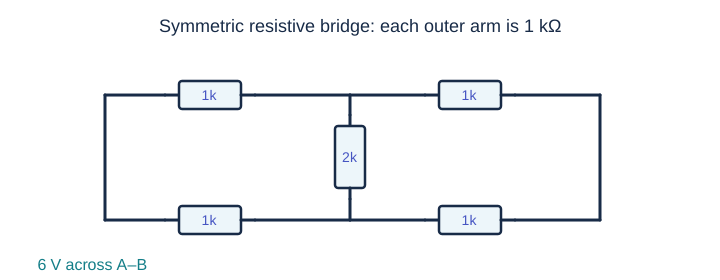
In the resistive bridge shown, four outer resistors are each 1 kΩ and a 2 kΩ resistor connects the midpoints C and D. A 6 V DC source is connected across A–B. Find the current through the 2 kΩ resistor.
Clean schematic redrawn for this practice question (not an official exam graphic).
YOUR RESPONSE
Detailed solution and exam tip
Answer: A
The upper and lower A–B branches each contain identical series resistors of 1 kΩ + 1 kΩ.
The midpoint voltage in both branches is exactly half the supply, so V_C = V_D = 3 V (relative to the low-potential rail).
The bridge resistor sees zero potential difference: I_{CD} = (V_C − V_D)/(2 kΩ) = 0.
Exam insight: A bridge is balanced when R₁/R₂ = R₃/R₄. The bridge-arm resistance then does not affect the midpoint balance.
QUESTION 03 OF 17
Dependent-source Thevenin
1 markMCQ
Source reference: GATE EE 2021 · EE Q4 · reworded for independent practice
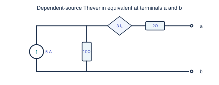
The network contains a 5 A current source in parallel with a 10 Ω resistor. A dependent voltage source raises the voltage by 3i₁ volts in the left-to-right direction, where i₁ (A) is the downward current through the 10 Ω resistor. A 2 Ω resistor leads to terminal a; terminal b is the reference node. Determine the Thevenin voltage and resistance seen at a–b.
Clean schematic redrawn for this practice question (not an official exam graphic).
YOUR RESPONSE
Detailed solution and exam tip
Answer: B
With a–b open, no current flows through the 2 Ω resistor. The 5 A source therefore drives i₁ = 5 A through 10 Ω.
The main node is V = 10×5 = 50 V. The dependent source adds 3i₁ = 15 V, giving V_th = 65 V.
To calculate R_th, open the independent current source and apply a 1 A test current entering terminal a. Then i₁ = 1 A, the 10 Ω drop is 10 V, the controlled-source rise is 3 V, and the 2 Ω drop is 2 V.
The test voltage is V_test = 10 + 3 + 2 = 15 V, hence R_th = 15 Ω.
Exam insight: Keep dependent sources active when finding Thevenin resistance. Use a test current or test voltage.
QUESTION 04 OF 17
Capacitor switching
1 markMCQ
Source reference: GATE EE 2010 · EE Q5 · reworded for independent practice
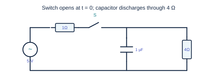
A 5 V DC supply feeds a 1 Ω series resistor and a switch. Beyond the switch, a 1 µF capacitor is connected in parallel with a 4 Ω resistor. The switch had been closed for a long time and opens at t=0. Find the magnitude of the capacitor current immediately after opening.
Clean schematic redrawn for this practice question (not an official exam graphic).
YOUR RESPONSE
Detailed solution and exam tip
Answer: B
Before switching, the capacitor is an open circuit at DC steady state. The 1 Ω and 4 Ω resistors form a voltage divider.
The capacitor voltage is V_C(0⁻)=5×4/(1+4)=4 V.
Capacitor voltage is continuous: V_C(0⁺)=4 V. When the switch opens, the capacitor discharges through only the 4 Ω resistor.
The initial discharge-current magnitude is |i_C(0⁺)|=4/4=1 A.
Exam insight: For switching circuits, first obtain the pre-switch steady state, then apply capacitor-voltage continuity.
QUESTION 05 OF 17
Balanced three-phase loads
1 markNAT
Source reference: GATE EE 2022 · EE Q34 · reworded for independent practice
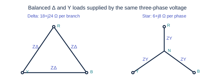
A three-phase source provides 100√3 V RMS line-to-line at 50 Hz. It supplies two balanced loads in parallel: a delta-connected load with branch impedance ZΔ = 18 + j24 Ω and a star-connected load with phase impedance ZY = 6 + j8 Ω. What is the RMS line current in amperes? Give the nearest integer.
Clean schematic redrawn for this practice question (not an official exam graphic).
YOUR RESPONSE
Rounded values are accepted within a small tolerance.
Detailed solution and exam tip
Answer: 20.0000 A
Convert the delta load to its equivalent balanced star: ZΔ,Y = ZΔ/3 = (18+j24)/3 = 6+j8 Ω.
This equivalent load is in parallel with the existing star phase impedance 6+j8 Ω. Consequently Z_phase = (6+j8)/2 = 3+j4 Ω, whose magnitude is 5 Ω.
The phase (line-to-neutral) RMS voltage is V_phase=(100√3)/√3=100 V.
Hence the star-equivalent line current is I_L=100/5=20 A.
Exam insight: For balanced three-phase circuits, convert Δ to Y first to simplify per-phase analysis.
QUESTION 06 OF 17
Positive-sequence phasors
1 markMCQ
Source reference: GATE EE 2014 · EE Q6 (supplied set 3) · reworded for independent practice
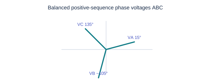
A balanced star-connected three-phase system follows phase sequence ABC. The voltage of line A relative to neutral is V_AN=10∠15° V. Determine the line-to-line voltage V_BC.
Clean schematic redrawn for this practice question (not an official exam graphic).
YOUR RESPONSE
Detailed solution and exam tip
Answer: C
With positive ABC sequence, V_BN=10∠(15°−120°)=10∠−105° V.
For a positive-sequence system, the line-to-line phasor V_BC leads the phase phasor V_BN by 30° and has √3 times its magnitude.
Thus V_BC=10√3∠(−105°+30°)=10√3∠−75° V.
Exam insight: In positive sequence, V_AB=√3 V_AN∠30°, V_BC=√3 V_BN∠30°, and so on.
QUESTION 07 OF 17
Complex power signs
1 markMCQ
Source reference: GATE EE 2013 · EE Q8 · reworded for independent practice
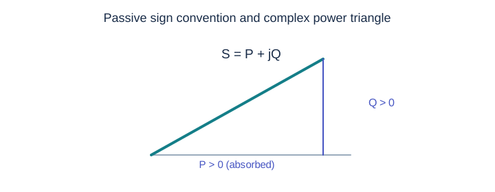
A one-phase load has terminal voltage 100∠60° V. The measured current from the load toward the source is 10∠−150° A. With power absorption defined using current entering the load, how does the load exchange real and reactive power?
Clean schematic redrawn for this practice question (not an official exam graphic).
YOUR RESPONSE
Detailed solution and exam tip
Answer: B
The given current direction is from the load to the source. Under passive sign convention, the current entering the load is I_L = −10∠−150° = 10∠30° A.
The load’s complex power is S=V I_L* =100∠60° ×10∠−30°=1000∠30° VA.
Therefore P=1000 cos30°≈866 W>0 and Q=1000 sin30°=500 var>0. Both are absorbed.
Exam insight: If a measured current arrow points out of the load, reverse its direction before computing absorbed complex power.
QUESTION 08 OF 17
Ideal network elements
1 markMCQ
Source reference: GATE EE 2025 · EE Q19 · reworded for independent practice
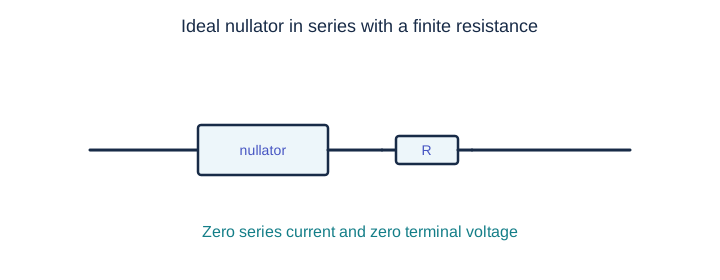
An ideal nullator imposes zero terminal voltage and zero through-current simultaneously. What is the equivalent behavior when a nullator is connected in series with a finite resistor R?
Clean schematic redrawn for this practice question (not an official exam graphic).
YOUR RESPONSE
Detailed solution and exam tip
Answer: B
Series elements carry the same current. The nullator requires i=0, so the resistor also carries zero current and has v_R=iR=0.
The nullator itself has v_N=0. Thus the series pair has v_terminal=v_N+v_R=0 and i_terminal=0.
Both nullator constraints remain, so the equivalent is a nullator rather than a generic open or short.
Exam insight: A nullator requires both v=0 and i=0. An ordinary short fixes only v=0; an ordinary open fixes only i=0.
QUESTION 09 OF 17
First-order RC step response
2 marksMCQ
Source reference: GATE EE 2026 · EE Q43 · reworded for independent practice
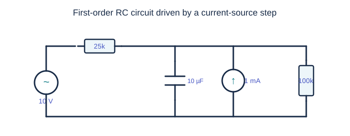
A 10 V DC source connects through 25 kΩ to a node with a 10 µF capacitor and a 100 kΩ resistor to ground. A 1 mA current source, directed upward into the node, turns on at t=0. Identify the capacitor voltages at t=0⁺, 0.50 s, and ∞.
Clean schematic redrawn for this practice question (not an official exam graphic).
YOUR RESPONSE
Detailed solution and exam tip
Answer: B
Before t=0, the 1 mA source is off and the capacitor is open at steady state. Voltage division gives v_C(0⁻)=10×100/(25+100)=8 V.
After the source turns on, the DC node satisfies (v−10)/25k + v/100k = 1 mA; solving gives v_C(∞)=28 V.
With ideal voltage and current sources deactivated for resistance, R_th=25k∥100k=20 kΩ. Therefore τ=R_th C=20k×10µ=0.20 s.
Use v_C(t)=28+(8−28)e^(−t/0.2). At 0.5 s this is 28−20e^(−2.5)=26.36 V.
Exam insight: Check both endpoint values (at 0⁺ and ∞) before evaluating the exponential.
QUESTION 10 OF 17
Two-port Norton equivalent
2 marksNAT
Source reference: GATE EE 2015 · EE Q56 (supplied set 1) · reworded for independent practice
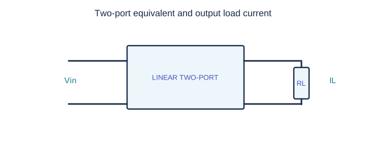
A linear two-port behaves as follows: with 10 V applied to its input and its output short-circuited, the output short-circuit current is 4 A. With 5 V applied at the input and a 1 Ω resistor at the output, the load current is 1.25 A. Find the current through a 2 Ω output load when the applied input becomes 3 V.
Clean schematic redrawn for this practice question (not an official exam graphic).
YOUR RESPONSE
Rounded values are accepted within a small tolerance.
Detailed solution and exam tip
Answer: 0.5455 A
For the same linear two-port, short-circuit current scales with input voltage: I_N(5 V)=4×5/10=2 A.
Let the Norton output resistance be R. With a 1 Ω load, current division gives 1.25=2×R/(R+1), so R=5/3 Ω.
For a 3 V input, the Norton current is I_N(3 V)=4×3/10=1.2 A.
With the 2 Ω load, I_L=1.2×(5/3)/(5/3+2)=6/11≈0.5455 A.
Exam insight: Norton equivalent makes short-circuit-current measurements especially convenient.
QUESTION 11 OF 17
RC discharge and charge
2 marksNAT
Source reference: GATE EE 2016 · EE Q37 (supplied set 2) · reworded for independent practice
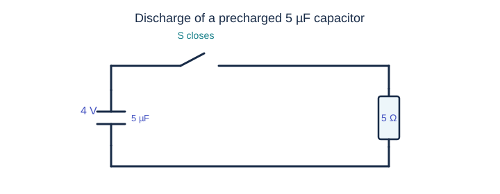
A 5 µF capacitor initially has 4 V across it. At t=0 a switch connects the capacitor across a 5 Ω resistor. Find the charge lost by the capacitor between t=25 µs and t=100 µs, in microcoulombs.
Clean schematic redrawn for this practice question (not an official exam graphic).
YOUR RESPONSE
Rounded values are accepted within a small tolerance.
Detailed solution and exam tip
Answer: 6.9913 µC
The RC time constant is τ=RC=5×5 µs=25 µs.
The initial capacitor charge is q(0)=CV=5 µF×4 V=20 µC.
During discharge, q(t)=20e^(−t/25µs) µC.
The charge lost is q(25µs)−q(100µs)=20(e^(−1)−e^(−4))≈6.9913 µC.
Exam insight: Charge lost is the difference between charge at the two specified instants—not the initial charge minus the final charge.
QUESTION 12 OF 17
RC zero-crossing
2 marksNAT
Source reference: GATE EE 2020 · EE Q45 · reworded for independent practice
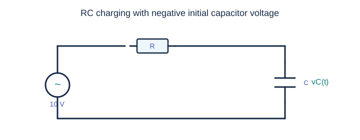
A resistor and capacitor are connected in series to a 10 V DC supply through a switch. When the switch closes at t=0, the capacitor voltage crosses 0 V at t=0.4τ, where τ is the RC time constant. By what absolute percentage must the initial capacitor voltage change to move the zero crossing to t=0.2τ? Round to two decimals.
Clean schematic redrawn for this practice question (not an official exam graphic).
YOUR RESPONSE
Rounded values are accepted within a small tolerance.
Detailed solution and exam tip
Answer: 54.9834 %
For a first-order charging circuit, v_C(t)=10+(V₀−10)e^(−t/τ).
At a zero crossing t=aτ, setting v_C=0 gives V₀=10(1−e^a).
Originally V₀=10(1−e^0.4)=−4.91825 V. To cross at 0.2τ, the new initial voltage must be V₀′=10(1−e^0.2)=−2.21403 V.
The requested absolute percentage change relative to the original initial voltage is 100×|V₀′−V₀|/|V₀|≈54.98%.
Exam insight: Both initial voltages are negative. Take the absolute change and divide by the magnitude of the original initial voltage.
QUESTION 13 OF 17
Inductor current continuity
2 marksMCQ
Source reference: GATE EE 2007 · EE Q61 · reworded for independent practice
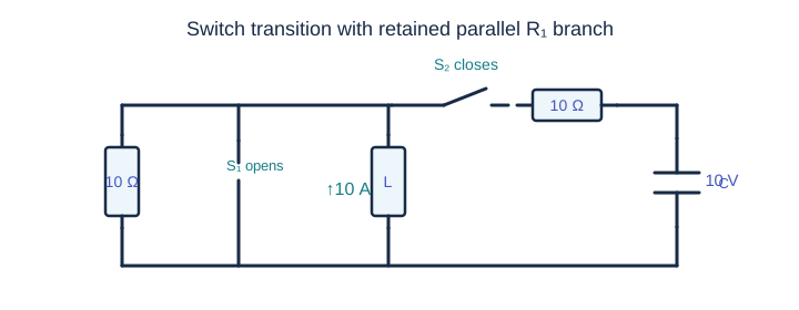
In the switched network shown, a 10 Ω resistor R₁, an inductor, and a shunt switch S₁ are connected in parallel. S₁ is initially closed, while S₂ is open. The inductor current immediately before switching is 10 A upward and the capacitor voltage is +10 V (top positive). At t=0, S₁ opens and S₂ closes, connecting the inductor node to the capacitor through a second 10 Ω resistor. Find the capacitor current magnitude and the inductor voltage magnitude at t=0⁺.
Clean schematic redrawn for this practice question (not an official exam graphic).
YOUR RESPONSE
Detailed solution and exam tip
Answer: D
The inductor current cannot jump. It remains 10 A upward at t=0⁺. The capacitor voltage also cannot jump and remains 10 V.
S₁ is open, but the parallel 10 Ω resistor R₁ remains connected. The inductor injects 10 A into two paths: R₁ and the R₂–C branch.
The shunt switch has opened, so the two 10 Ω resistive paths must both appear in KCL at the inductor top node.
KCL gives V_L/10+(V_L−10)/10=10, yielding V_L=55 V and i_C=(55−10)/10=4.5 A.
Exam insight: Always freeze inductor current and capacitor voltage at switching. Retain both 10 Ω branches when setting up post-switch KCL; S₁ is a shunt switch, not a switch in series with R₁.
QUESTION 14 OF 17
Maximum average power transfer
2 marksMCQ
Source reference: GATE EE 2017 · EE Q30 (supplied set 2) · reworded for independent practice
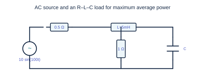
A sinusoidal voltage source v(t)=10 sin(100t) V has internal resistance R_s=0.5 Ω. It drives a load consisting of a 5 mH inductor in series with a parallel combination of 1 Ω and a capacitor C. Choose C so that average power transfer to the load is maximized.
Clean schematic redrawn for this practice question (not an official exam graphic).
YOUR RESPONSE
Detailed solution and exam tip
Answer: D
The angular frequency is ω=100 rad/s, so X_L=ωL=100×0.005=0.5 Ω.
Let x=ωCR with R=1 Ω. The parallel impedance is Z_(R∥C)=1/(1+jx)=(1−jx)/(1+x²) Ω.
To match the real source resistance R_s=0.5 Ω and cancel its zero reactance, require Re(Z_load)=0.5 and Im(Z_load)=0. This gives 1/(1+x²)=0.5 ⇒ x=1.
Thus C=x/(ωR)=1/(100×1)=0.01 F = 10 mF. At x=1, the parallel branch has reactance −0.5 Ω, canceling the series inductor.
Exam insight: For maximum AC power transfer, match the load impedance to the complex conjugate of the source impedance.
QUESTION 15 OF 17
Dielectric loss and tan δ
2 marksMCQ
Source reference: GATE EE 2011 · EE Q28 · reworded for independent practice
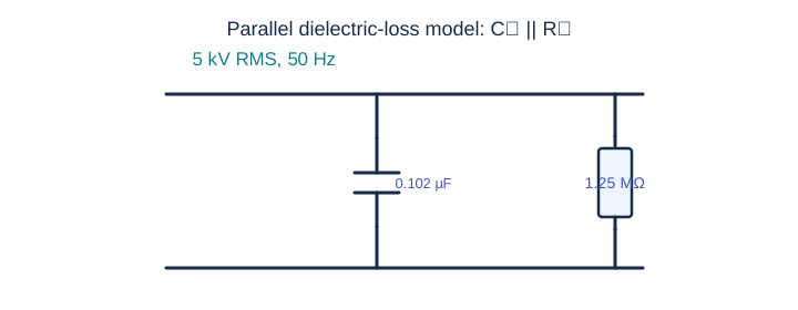
A lossy capacitor rated for 5 kV RMS, 50 Hz can be modeled as an ideal C_p=0.102 µF in parallel with a loss resistance R_p=1.25 MΩ. Find its dielectric power loss and the loss tangent tan δ at the rated voltage.
Clean schematic redrawn for this practice question (not an official exam graphic).
YOUR RESPONSE
Detailed solution and exam tip
Answer: C
In the parallel model, resistive real-power dissipation is P=V_rms²/R_p=(5000²)/(1.25×10⁶)=20 W.
The dielectric loss tangent is the ratio of resistive conductance to capacitive susceptance: tan δ=G/B_C=(1/R_p)/(ωC_p)=1/(2π f R_p C_p).
Substituting values gives tan δ≈1/(2π×50×1.25×10⁶×0.102×10⁻⁶)≈0.02497≈0.025.
Exam insight: Use RMS voltage in the resistor power formula. Loss tangent is dimensionless.
QUESTION 16 OF 17
Two-port data interpretation
2 marksMCQ
Source reference: GATE EE 2012 · EE Q50 · reworded for independent practice
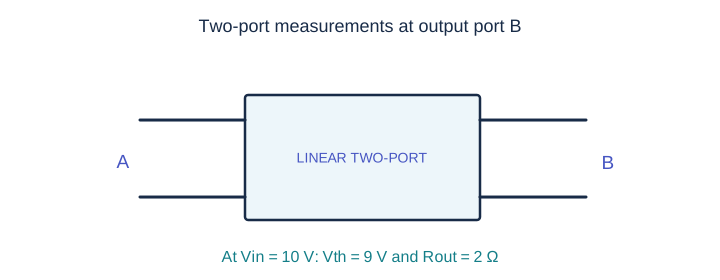
A two-port network has the following output measurements when input port A is driven at 10 V DC: a 1 Ω load at output port B draws 3 A, and a 2.5 Ω load draws 2 A. In another measurement, with input voltage 6 V and a 1 Ω output load, the load current is 7/3 A. Based on these observations, find the open-circuit output voltage when the input voltage is 8 V. (Use the measured affine input-to-output behavior.)
Clean schematic redrawn for this practice question (not an official exam graphic).
YOUR RESPONSE
Detailed solution and exam tip
Answer: C
For 10 V input, represent the output by V_th in series with R_th. Measurements give V_th/(R_th+1)=3 and V_th/(R_th+2.5)=2.
Solving 3(R_th+1)=2(R_th+2.5) gives R_th=2 Ω and V_th(10 V)=9 V.
With input 6 V and load 1 Ω, the implied output open-circuit voltage is V_th(6 V)=(7/3)(2+1)=7 V.
Using the affine relationship through these measurements, V_th(V_A)=0.5V_A+4. Therefore V_th(8 V)=0.5×8+4=8 V.
Exam insight: Accuracy note: the given 6 V measurement is inconsistent with a homogeneous, source-free linear two-port (which would scale output by 6/10). The specified measurements imply an internally biased/affine response. This solution follows the measured data and the intended source answer; students should be told about the assumption.
QUESTION 17 OF 17
Two-port output loading
2 marksMCQ
Source reference: GATE EE 2012 · EE Q51 · reworded for independent practice
Use the same two-port data as Question 16. With a constant 10 V applied at input port A, determine the output current drawn by a 7 Ω resistor connected across port B.
Clean schematic redrawn for this practice question (not an official exam graphic).
YOUR RESPONSE
Detailed solution and exam tip
Answer: C
From the two measurements at 10 V input, the output Thevenin voltage is V_th=9 V and output Thevenin resistance is R_th=2 Ω.
The new load is R_L=7 Ω. Therefore I_L=V_th/(R_th+R_L)=9/(2+7)=1 A.
Exam insight: Once a Thevenin equivalent has been determined for a fixed input, changing the load requires only a series-current calculation.
ATTEMPT COMPLETE
Your results and answer key
Scored practice summary.
—Net marks / 26
—Correct
—Incorrect
—Skipped
Numerical answers allow small rounding tolerances; standard GATE MCQ negative marking applies. The answer key is independently prepared and is not issued by the GATE organizing institute.